• Home
  • Gallery
    • Gallery
    • High-Res Gallery
  • Process
    • Neural Project
    • Doomfletch Walkthrough
  • About
  • Blog

Z. Schwartz

  • Home
  • Gallery
    • Gallery
    • High-Res Gallery
  • Process
    • Neural Project
    • Doomfletch Walkthrough
  • About
  • Blog

Divine Ire Pt. 1

This is sort of a follow up to the previous blog post involving electrical art. Divine Ire is a favorite skill of mine (from the game Path of Exile), and so this would be a good effect to play around with more particle system things. Same basis with some additions. One is the line-based beam discharge, that is some module calculations to have the bolt form in a spiral. E.g xy coordinates are cos/sin of radians from the execution index multiplied by a scalar; z is the index times a scalar for height per turn, the return of that times the radius). I also used the opportunity to do some environment mood lighting + bit of modeling & texturing.


Next update will include some visual revisions to the mesh emitter, possibly more destruction, & the original version (not automaton).

divine1.gif
divine2.gif
tags: UE4, niagara, divine ire, automaton, path of exile, 3d art
Monday 04.13.20
Posted by Zachary Schwartz
 

Electricity & Mjölnir

A few years ago I posted a blog with a wireframe screenshot of the rare hammer Mjolner. A couple months ago I opened the file again to take a look, and then the Delirium league was about to be released; so I opened again. Anyway, let's get that lightning to sing.

For the lightning/electricity itself there’s many considerations. Similar to the neural project, I want the setup to be nice and procedural. As a note of difference in this system it was more about using ribbon particles in Niagara. I had done some procedural lightning in the past, for Chronicles of Elyria —- although it was created using Cascade. In that rendition there was far more blueprint involved, and it was more focused on the primary bolt with one split. Naturally some of operations like setting beam tangents are applicable in the module scripting rather than BP. Not all of the functions necessarily have exact crossover , but there’s a lot of additional vector/matrix functions available in Niag.

hammerrot2.gif
hammerrot1.gif


Visual components can be broken down to Materials/Shader, particle system, blueprint, additional scene lighting.
The shaders aren’t overly complex, but the main goal is having a parametric band/linear gradient that runs along the polystrip that is our ribbon. Using some functions we’ll compose a gradient/2d line, with the uv coordinates being offset by noise. Keep in mind my shader is leveraging function based noise rather than sampling a texture object, hence higher instruction count. I could also just encode the functional noise to a texture, or author the noise outside of the editor & import for use. We’ll start off with one coordinate offset from the initial noise (simplex), and then another simplex with 1-2 levels, which we can integrate into the main tendril in a few ways. By inverting the gradient we can power it as to create a shell/halo, which can be closed arcing sub-tendrils —- or, keep the initial values to create mini-offshoots. I’m still playing ‘round w/ the shader. Interestingly the effect you get when panning the noise is something like a flame combustion stream.

The emissive output is the float result multiplied by blackbody (lightning temperatures can reach 30,000 C), but the final intensity is a fractional multiplier due to the sensitivity of the post process to bloom & autoexposure. For the presentation that’s fine.

1.PNG tendril1.PNG
shell1.gif
line1.gif
shader1.PNG

For the electricity on the hammer mesh there’s various ways to go about it. I did a hybrid approach, which is not particularly optimized. Essentially what we’ll do is an offscreen capture of a particle system with the main shader, and then write that simulation to a texture, which gets applied onto a shell of the static mesh via tangent space. Since the coordinates are not contiguous the tendrils hop between uv islands at the boundary, but it’s not a big deal since electricity can appear rather erratic anyway. That said it needs improvements. The more physical approach is something more analytical. which would be querying collision hits on the surface of the static mesh, and then spawning the particles along the spline; or doing a lookup of the barycoords for an array of triangles on the mesh surface. In the latter case you’d optimally deal with a decomposition of the high-poly model, so that you can quickly sort through the series of nearest vectors. Etc. I’ll probably expand into that later on.

Onto the particle system portion, there’s really a lot. The essentials come down to the system, the emitters, and the modules. The system contains all of our emitters, and the emitters leverage modules. The first step is an emitter which starts at a point approximate to the surface of the static mesh (can do a random tri coord, weighted coordinate, or simply a numerical range within the bounding box), and then set a target position. For the purpose of testing I’m setting the target position by way of blueprint vector widget (you can drag the vector gizmo around, and its worldspace position gets set to a linked Niagara variable. The workflow is create a new variable on the emitter of the type you want (currently, at-least in 4.21 those are limited to float data types —- float, vec2, vec3, vec4, non arrays), with the User. namespace. Niagara’s namespace functionality is nice, but takes a bit getting used to.

bp1.PNG
bp2.PNG

Between these positions we do some logic to set all things on the ribbon renderer. For example the density of particles across the length; higher counts increasing the smoothness of the emitter spline, but requiring functional noise as a modulator. So on-top of the primary positions, I included an additive —- which is simply the sine of the normalized execution index, with a period over 1, and random coefficient. We can add some randomization onto that position w things like Gaussian random vector, but since the random will get called for each particle index you usually end up with a very erratic, but constant, offset. Other options are to multiply it by a curve, or use a spline handle calculation. We can supply with a 3d/curl noise, or assemble the points+handles on emitter initialization. However, with this approach, the algorithm is doing everything between 2 points, so if the bolt is calculated afterwards it can go right through collision objects. If the goal was to have it wrap, or change path then we’d do a collision query on ParticleUpdate perhaps. Some variation of an lsystem could work nicely for raytracing the vectors, but that’s another layer of complexity that I’m not doing for this iteration.


When the primary bolt is rendered, we step through a couple if statements & then if true, select that point as well as a couple other vectors to dispatch as an event write. The event write is a custom struc that you can simply add from the project UI. Anyway, I ran into an issue with ribbons sporadically returning a particle to the root… I thought hey maybe that would be due to a conflict with the acquire tag; thus I just give each ID a random integer (when an emitter is being used in a forloop method, acquire tag shouldn’t be rand). Next up I created a tracer emitter that reads the event, along with its data; things are done, mainly just a collision query in a direct line from the main bolt position to another position (the start position + direction with magnitude.) That direction is designated as a vector we get by taking the result of a spherical linear interpolation between the forward & right vector of the system owner. The alpha being a random range, and the mirrored direction being one axis * -1, with a random boolean as the selector. Re-write the data through our map.

The collision point will be the end positions of the secondary bolts. Those secondary bolts receive a similar set of algorithms as the primary bolt , but with some extra things to make them pop. Electrical discharges from the hammer mesh also leverage this logic, the only difference between that the start point is a random tri coordinate with a bias for top-down. Random ribbon width etc.

n1.PNG

The other material settings don't require a great degree of explanation. The textures & shader setup are pbr; textures were arranged in substance designer with some of the explicit maps being curvature & displacement (although for now the ground texture is just a modified photoscan). The volume fog comes in two flavors; one being simply enabled on the fog component, and the other being the volume fog shader model applied onto a sprite/geometry field. So I used the same method as a workaround; by way of a top-down render target texture for the particle system, & then applying it in the volume fog material. For VXGI propagation I sample that texture, with opacity, on an inverted single-sided plane. Right now I’m not worrying about the z-axis save for a 3d noise to break up lines; Regardless, it adds a proper element.

More to come

Thursday 04.02.20
Posted by Zachary Schwartz
 

Excerpt No. 2 Parametric

Wanted to do a quick follow up to the previous blog post with some clips of parameters being updated on the psystem. The main level of control corresponds to the largest element in the cochlear structure. Which would resemble that of a logarithmic spiral (according to some research the analytical model that fits the cochlea uses a type of polynomial/polylogarithmic  spiral, which may be closer to what I employed). Fittingly the name for the nervous structure in focus is the spiral ganglion. Although I set up the function for this both in Niagara & blueprint, there’s some advantages to generating the spline data in blueprint.


Here’s a couple clips of me tuning the radius, exponent, height, number of turns, neuron count.

In the radius modulation clip it’s apparent that there’s some amount of perturbation on the z-axis. To fit the rough/complex profile of spiral the height variable also gets multiplied by a float curve that can be tuned. This still needs refinement.

In the video below I have examples of me tuning a few of the shader parameters, as well as having a soundwave asset linked to the shader so that the frequency and amplitude map to the Z. The hair cells actually respond to the frequency spectrum respective to their location, from the base to apex. This is my first test; also in this video I had to overlay the track afterwards as I had recorded with a video-only software (timing is slightly off).

More to come

tags: cochlea, spiral ganglion, particle fx, UE4, realtime rendering, micro
Sunday 01.12.20
Posted by Zachary Schwartz
 

Excerpt No. 1 Neural Elements

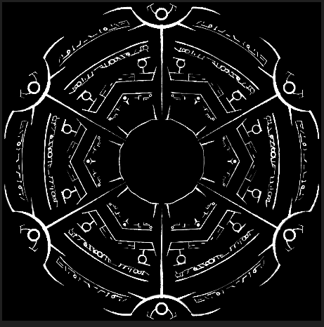
So I've been tinkering away at this project for some months now. I came across some images of the neural structure of a cochlea. I had the thought that it would be a good opportunity to delve into UE4's [still experimental] particle system --- Niagara. It ended up becoming something where I can explore various other methods for constructing the cochlea in its entirety, but emulating confocal microscopy being one of the ideas. The other is merging with a system that logically transforms soundwaves into the visual output; as well as being procedural enough so that a user can interface with it.

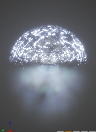
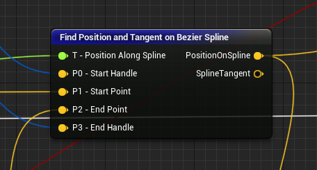
To start the primary simulation type is CPU based, i.e mesh-renderer and ribbon renderer. Mesh particles don't enable with GPUsim. So there's a lot of logic going on to generate the transforms for the neurons; Primarily constructing a control spline via functions I set up in blueprint, then accessing that in Niagara to work with the pertinent vectors.

On Somata & Optimization

One of the more immediate problems to solve relates to the most effective method for representing the shapes, without exceeding rendering budget. In the case of the neuron cell body I started off with pre-tessellated static mesh that roughly fits the limit, but it was at least 100 triangles for a decent amount of curvature. Times the number of particles/instances that adds up. Why not mesh LoDs? You'll immediately find that the most common method for LoDing (level of detail) -- reduced polycount versions of the original -- doesn't actually function in mesh particle data/space. In the current implement LOD-0 is the only thing that gets rendered, which means that's a no-go for managing triangles. So there's a number of other options.

I thought hey, why not just tessellate? Ok well the first point would be to have starting geometry of a low triangle count, that I can also morph into a sphere. I opted for an octahedron (tetrahedron should also work, but the base geometry would have a higher profile disparity at the lowest tessellation). 8 triangles, not bad. I enabled tessellation, piped a scalar in & checked wire-frame. Funnily enough wireframe mode doesn’t render tessellated triangles when the static mesh is in Niagara particle space. Cascade mesh particles are fine. We get to either use flat tessellation or PN triangles (spline based method that smooths). PN triangles don’t really work with mesh particles it seemed, & even if it would it's not like I would get the displacement controls I desired.

So flat tessellation, then some shader math. Vertex normals * .5, retrieve its vector length, cosine of that + n *x multiplied by the vertex normals. Then multiplied by the local scale. In the case of instances you can normally retrieve that scale by appending the lengths of the xyz vectors, which are transformed from local space into world space. However, the local-to-world transform function is only supported by vertex, compute or pixel shader. Since we're doing things in the domain/hull shader my workaround is to pass the transformed vector through the vertex shader (via customizedUV). Simple & effective in a variety of cases. That said if you're dealing with vec/float3s you'll need to utilize two customizeduv channels, since you unpack via a texcoord (which is a vec2).

OctatoSphere.gif

Finally, to 'lodify' we simply linear interpolate between two scalars (e.g 0 and the highest tessellation multiplier), with the alpha input being the distance from the camera position to absolute world position. Vector length of cam pos - absworldpos, minus x, divided by y, saturate. The displacement function obviously goes into worlddisplacement pin.

I would like to refine the function but this works for getting a base to apply additional displacements. Another option is use the tetrahedron as as a surface domain bounding volume for rendering the cell body primarily via the pixel shader —- e.g via some version of spheregradient3d. We could then cut the base tri-count in half & choose whether or not to include tessellation. There are some complexities to deal with there. Either way it’s an option, & I’m actually already using some of that for the ‘nucleus’ portion.

Procedural Mesh Creation

One of the enjoyable things to play with has been UE4’s procedural mesh generation functionality. Typically you would just create the base models/geometry in your DCC(digital content creation software) of choice. E.g model with that toolset & export to file for import into the engine. In this case I wanted to play around with the aspect of generating topology programatically. The basic method is construction script with logic to assemble the data necessary to create ‘mesh sections’. Vertices, triangles, normals, tangents, uvs. Some things in the works are the octahedron for cell body, synaptic planes, path deforming shape profile (e.g cochlear ducts/body).

Below are a couple example snippets of vertex/triangle arrays. The algorithms are a bit dirty/not refined for a variable geodesic yet, but I just needed the 8-tri octa in this case. =] There are a variety of ways to solve for a particular topology. For example the simplest vertex function for a straight up octahedron could just be be a switch-on-int statement with the 6 respective direction vectors. The harder thing seems to be setting up a good algorithm for the triangle array.

Also a note on grids/planes. I set up an algorithm for a variable tessellation plane to work with, and it was still comparatively slower than a function called Create Grid Mesh (example of having code that’s already cooked/done in C++ vs entirely bp nodes). A way to do certain shapes like a tube is create a grid mesh section, then operate on those vertices before remaking the arrays, & calling create procedural mesh section. Calculate mesh tangents is another nice built in function for quickly getting the smoothed normals+tangents for the section.

procmesh2.gif
View fullsize OctaVerts.PNG
View fullsize Tris.PNG
cells3.gif

Still looking into some techniques for the cell-packing, perhaps something with distance fields. At the moment it’s based on curve derived transforms, in a [3d] array with offsets. In the next blog post I’ll likely go over this more in depth.

tags: unreal engine, niagara, particle simulation, neural, rendering, realtime, shaders, music, techart
Thursday 01.02.20
Posted by Zachary Schwartz
 

The Three Dragons Triptych + Preview

Hey all. I had my hands full for around 1.5 weeks so I didn't get much time to work on the piece; instead ended up working on it for the remaining time, hence the post being 1 week later than usual. Anyway, hope you like it. =} I'll be posting some extra things in the coming weeks along with my normal renders.

I included a cropped version of a scene in the works as well.

ThreeDragons
View fullsize LeftDragon.jpg
View fullsize MidDragon.jpg
View fullsize RightDragon.jpg
View fullsize entrance.jpg


Saturday 07.11.15
Posted by Zachary Schwartz
 

Archives/Elreon's Hideout, Preview & More

     It's been a hectic past couple weeks, but I have an extra render for you guys; as well as a preview for another upcoming model. Apart from the art, I added a poll page for anyone who wants to give their feedback on future pieces (any suggestions are welcome). You can either use the contact form to send me a message, the comment section here, the one in the poll after you vote, or any other social media site (reddit, dA, etc). :}

     This render is actually something done with an existing PoE piece --- one I worked on back when the Forsaken Masters expansion/patch was hitting. I revised it with an extended room for this one, and a couple other changes. There's a couple errors I spotted post-render, but that will have to do for now. =p

     For the moment I changed my Patreon to a single 2 dollar pledge, absent patronage. So I'll be posting everything up on my site, and if you'd still like to donate I'd appreciate it. If I get any patrons in the future then I can update pledges & do polls on what viewers would like regarding this.

     Look forward to the following updates in the coming weeks/months. =}


archives
View fullsize Infopasses.jpg
View fullsize viewport1.jpg
Friday 06.19.15
Posted by Zachary Schwartz
 

Doom Fletch, Royal Bow + Walkthrough

I have a new render for viewers, as well as a walkthrough on the process. =} Hope you all enjoy.

I'll also be posting a preview for the next pieces, as well as some polls really soon.


doomfletch
Friday 06.05.15
Posted by Zachary Schwartz
 

Apep's Rage & First Blog Post


Welcome to my archives. A site where one may visit galleries of creation, and see the process by which I evolve. Being my initial blog post --- as well as a greeting --- I hope the viewers enjoy what they find. Atziri's Acuity is a 3d rendition of a concept seen in the game Path of Exile, and my foray into the realm of Patreon. Apep's Rage is the follow-up in the exhibit, and you can download the 3k render by clicking the image below.

If you're a patron or just someone visiting for the first time, I thank you for showing your interest --- and hope you enjoy the site. Here you'll find short post about what I'm working on, the occasional [link to] polls, and other updates that I'll be posting in conjunction with Patreon.

I hope you enjoy the beginning of my exhibits. =}

Apep's Rage

Apep's Rage

Friday 05.22.15
Posted by Zachary Schwartz